June 28, 2026
Connector Elements: More Powerful Than You Think
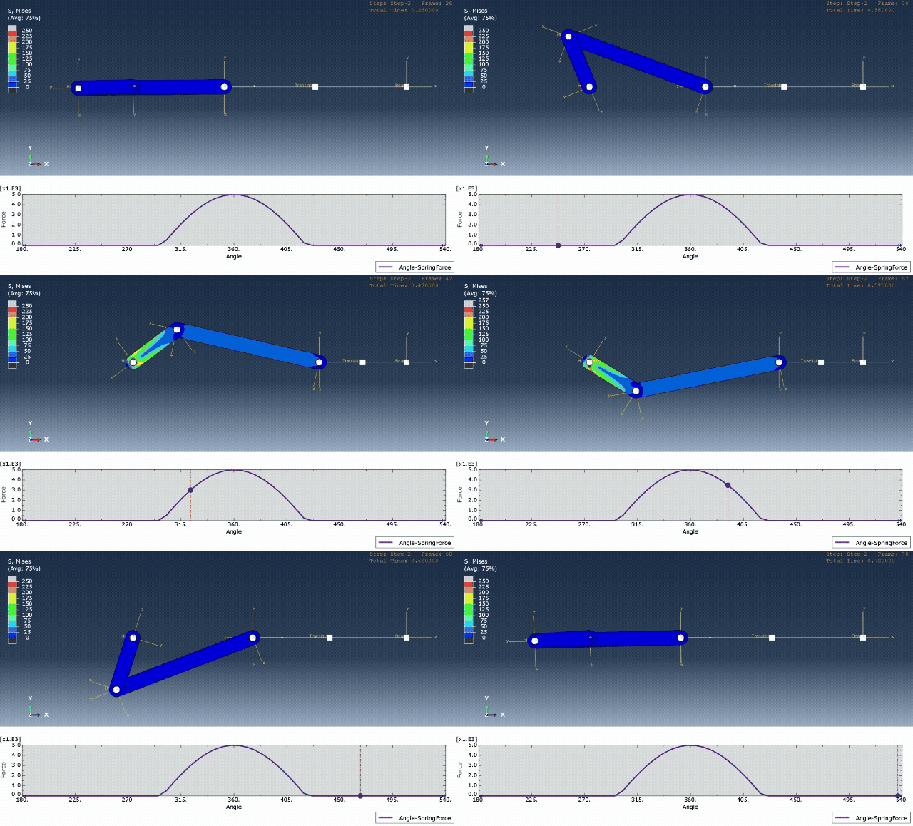
Advanced FEA Modeling Series #1
When engineers start building mechanism models, the first instinct is often: model every pin, model every bearing, model every contact pair. But that's not always the best approach.
A good finite element model does not necessarily represent every geometric detail. A good model represents the correct physical behavior.
For this benchmark study, I built a simple crank-slider mechanism with hinge joints, translational motion, gap behavior, and nonlinear spring interaction.
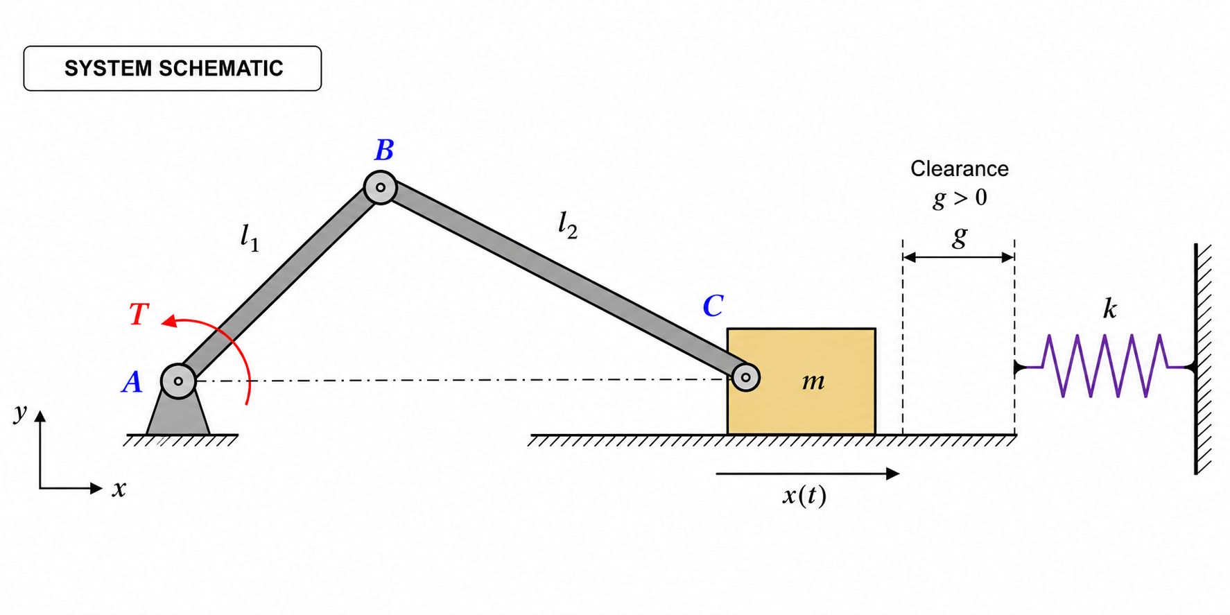
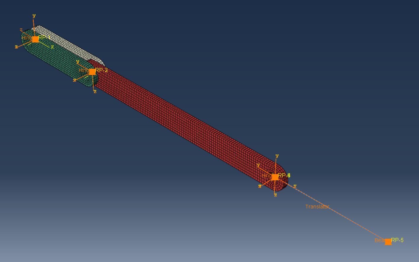
Instead of modeling all interfaces explicitly, I used Abaqus Connector Elements:
- Hinge connectors for the revolute joints
- A translator connector for the slider motion
- Nonlinear connector stiffness to represent contact and separation with the spring
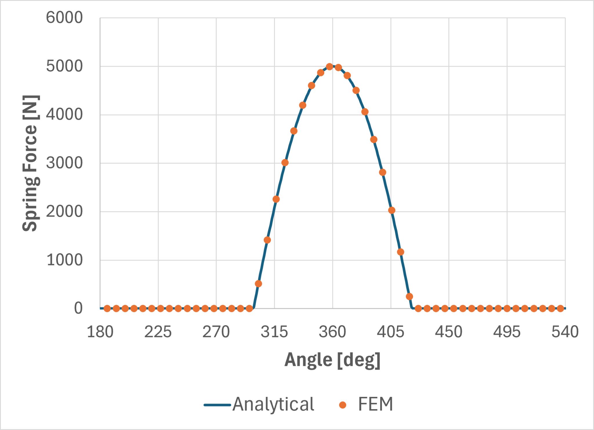
The model was then validated against an analytical solution. The result: the FEM and analytical force predictions matched almost perfectly.
Why this matters
This small benchmark highlights why connector elements are so valuable. They allow us to:
- Control individual degrees of freedom
- Define stiffness and damping
- Introduce nonlinear behavior
- Add limits, stops and failure criteria
- Reduce model complexity dramatically
Most importantly, they help us model behavior instead of geometry. And in many engineering problems, that distinction makes all the difference.
If you would like to learn more about connector elements and how they are modeled within Abaqus CAE, see the Fidelis Engineering Associates reference.
Originally posted on LinkedIn.